Mid Brace #FB-1910 for Fall Ban Roof Stanchions
Mid Brace for US Stanchions #FB-1910 | Fall Ban Roof Perimeter Safety Rail Cable Guard Systems
The Fall Ban Mid Brace purpose is to maintain correct cable height at all times when using the Fall Ban Stanchions in a Cable Guard roof perimeter fall protection kit, or other fall prevention setup. Mid Braces are to be installed between stanchions. If an area ends up with a greater than a 20ft interval, shorten the distance by adding another stanchion in that area. Stanchions may be installed consecutively with no Mid Brace in between if the distance requires or if necessary.
- Mid Brace US - 3
- OSHA Compliant
- Proudly Made In The USA

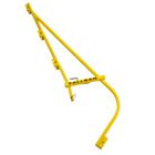
Fall Ban Mid Brace FB-1910 for maintaining correct cable guard height at all times throughout a cable run on roof perimeter fall protection and fall prevention setup at the leading edge. The purpose of the Fall Ban mid Brace component is to maintain correct cable height at all times when using the Fall Ban Stanchions in a Cable Guard roof perimeter fall protection kit, or other fall prevention setup. Mid Braces are to be installed between stanchions. If an area ends up with a greater than a 20' interval, shorten the distance by adding another stanchion in that area. Stanchions may be installed consecutively with no Mid Brace in between if the distance requires or if necessary.
- Manufacturer: Fall Ban
- Item: Mid Brace, US - 3 for Roof Stanchions
- Part Number: FB-1910
- Color: Safety Yellow (custom colors available per request)
- Dimensions: 48.75" x 4" x 5.75"
- Weight: 3.75 lbs
- Compliance: OSHA
Fall Ban Installation Instruction Reminder when using Mid Braces:
1.) Measure and mark off 10ft maximum intervals along the perimeter of the area to be protected, with 1 stanchion in each corner, and a stanchion every 2nd mark or 20ft on center. Mid Braces are to be installed between stanchions. If an area ends up with a greater than a 20ft interval, shorten the distance by adding another stanchion in that area. Stanchions may be installed consecutively with no Mid Brace in between if the distance requires or if necessary. The Mid Brace purpose is to maintain correct cable height at all times.

| SKU | FB-1910 |
|---|---|
| Manufacturer Part Number | FB-1910 |
| Manufacturer | FALL BAN |
| Weight | 3.75lb |
| Country of Manufacture | United States |
| Length | 48.75in |
| Width | 4in |
| Height | 5.75in |
Fall Ban Installation Instructions:
1.) Measure and mark off 10ft maximum intervals along the perimeter of the area to be protected, with 1 stanchion in each corner, and a stanchion every 2nd mark or 20ft on center. Mid Braces are to be installed between stanchions. If an area ends up with a greater than a 20ft interval, shorten the distance by adding another stanchion in that area. Stanchions may be installed consecutively with no Mid Brace in between if the distance requires or if necessary. The Mid Brace purpose is to maintain correct cable height at all times.
2.) Preassemble complete stanchions (attach a stanchion support plate and a stanchion to wall rest to a basic stanchion).


Position along the perimeter each with the configuration as needed:

-For an edge with a wall below use a standard stanchion

-Parapet Walls – assemble basic stanchion, an extension bar and a parapet clamp.

-Overhang (with no wall below) – assemble basic stanchion and an extension bar.
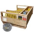
3.) Next lay out individual parts to be used, setting all the pieces about 10 feet from roof edge: (figure 2)

- Complete Stanchions (a complete stanchion includes a basic stanchion, a stanchion support plate and a stanchion to wall rest)
- Extension bars
- Diagonal braces
- Mid braces
- Anchor plates
- Corner roller assemblies (1 for each cable being used to achieve 42” minimum cable height, if a short parapet wall is present, only 1 or 2 cables may be needed.)
- Parapet clamps, etc.
When using a ladder to access the roof, a stanchion is needed 1 on either side of the ladder to create an access area. The cables need to be terminated on these stanchions. Allow ample space to exit the ladder. This same procedure is to be used for any other access area (Loading materials, removing debris, etc.) When the access area is not in use, cables or ropes should be used as a gate.

(Figure 3)
4) Pick a starting point, take a stanchion where there is a wall below for instance, set it on the roof edge and adjust the stanchion to wall rest so it slightly rests against the wall when the stanchion is in an upright position.
Once the first stanchion has been adjusted, set all stanchions to be installed on similar roof edge detail to the same adjustments.
5) Start installing components (EXAMPLE)
On a corner install a complete stanchion with 2 diagonal braces attached, 1 to face each direction. (figure 4)

Install minimum 2 screws in the top of the stanchion support plate, attaching the stanchion securely to the roof.
(2 additional anchors in the face may be necessary)
Secure each diagonal brace to the roof using 2 screws for each brace.
(Installer determines substrate acceptability for installation and accepts liability)
6) Go to the next mark to receive a stanchion (at 20 ft maximum spacing) and install another stanchion.
Proceed around perimeter and install all the stanchions and diagonal braces, 2 diagonal braces on each corner (Figure 4) and access area if fall protection is both sides of access area (Figure 3) and 1 diagonal brace at each termination point. (Figure 5)

(Figure 5)
Cable termination anchors may be installed if desired and/or required.
Cable can be terminated to stanchion or to a cable termination anchor. (Figure 3,5,6)

For the OSHA compliance testing we used 1 ½ inch # 12 screws when installing the stanchions, diagonal braces, mid braces, etc. The screw we used is made for insulation attachment on roof decks. The securement and attachment of this system is the responsibility of the installer, but we recommend always using new, no smaller than 1 ½ inch #12 screws to install the Fall Ban System and be cautious not to strip out the screw heads, this will make removing the screws no problem during disassembly.
You will have multiple possibilities for attaching the cable to terminate. Below are just a few examples
7) Unroll a ¼ inch cable along the perimeter of the roof. An easy way is to secure the end of the cable either at the stanchion or a cable termination anchor (figure 7). Put a broom handle through the roll of cable, hold the broom handle on both sides of the roll of cable, and walk along the perimeter to unroll the cable along the entire area to be protected.
Hook a cable to a cable termination anchor. (figure 7)

8) Next, start where the cable was secured and hook the cable to the top cable holder on each stanchion (figure 8)(or a lower cable holder if only 2 cables are being used), whatever is required to achieve a minimum of 42” height of top cable) Pull the cable fairly tight as you go all around this area and put a cable clamp on the holding side of the last stanchion (figure 9) to hold the cable taut while the remaining cables are set in place.

Another option is when you get to the last stanchion simply turn the cable down to the next lower cable anchor (figure 10) and finish unrolling that roll of cable back towards where you started, when your cable comes the end connect the end of one cable with the beginning end of another roll of cable using 2 cable clamps (when installing turn the tightening sides of the clamps in opposite directions) (Figure 11) pull cable taut while hooking onto each stanchion. When you get to the end pull cable taut and install a cable clamp on the holding side of the last stanchion. Repeat this process until all the cables being used are installed.

Loop and hook cable back to itself and hook a ratchet puller to a cable termination anchor.

This shows a stanchion with cable attached to the top cable anchor going left, a cable coming from left and hooking 2nd cable anchor turn down going to 3rd cable anchor and going left, and a ratchet puller hooked cable center of 2nd and 3rd cable anchors down to a cable termination anchor (figure 10)
Use ratchet pullers to tighten cables
Now to tension (tighten) the cables.

9) Tensioning Cables
To tension the cables, leave the J Hooks (on the mid braces) loose and hook the 15 lb. cable weight to the top cable halfway between a stanchion and a mid-brace and tension until the cable height (from the mounted surface) at the weight is within 2” of the cable height at a correlating stanchion.
Hook the weight on the next cable and tension in the same manner. If using 3 cables, tension the third cable the same way. It may be necessary to readjust the first and second cable tension after tightening the third cable. After cables have been tensioned, install a 2nd cable clamp at each cable termination (figure 12) and tighten the J Hooks on the mid braces.

Reminder: Check cable tension DAILY and re-adjust if necessary. Document actions in the daily log book. Tightening/Tensioning more is acceptable but may damage the wooden nailers and/or framing lumber. While Making your daily inspection, visually inspect the rod end and the swivel on each diagonal brace. On the diagonal brace, the rod end swivel is not meant for adjustment, its purpose is to rotate and swivel. During assembly and dismantling the rod end may be moved, exposed thread should never exceed 1/2 inch.